Turn on suggestions
Auto-suggest helps you quickly narrow down your search results by suggesting possible matches as you type.
Showing results for
- Good Sam Community
- Everything RV
- Technical Issues
- House battery life
Options
- Subscribe to RSS Feed
- Mark Topic as New
- Mark Topic as Read
- Float this Topic for Current User
- Bookmark
- Subscribe
- Mute
- Printer Friendly Page
House battery life
Options
- Mark as New
- Bookmark
- Subscribe
- Mute
- Subscribe to RSS Feed
- Permalink
- Report Inappropriate Content
Mar-27-2021 07:57 AM
For several years now I have been conducting a battery life expectancy test with my diesel motorhome. In January 2015, we arrived at Quartzsite for a winter stay, our first shot at Q. Shortly after arriving, it became obvious my house batteries were not in shape for a long boondock stay. I have four 6V house batteries, 2 each in series, connected in parallel. I disconnected all four and tested voltage and it seemed I had two low batteries out of the four. Since I was driving into Phoenix anyway, I stopped at the Interstate Battery store along I10 and bought 2 new GC2-XHD-UTL, 232Ah deep cycle batteries which I installed upon my return.
Of course, best laid plans and all that, I still did not have sufficient power and (since I was not going to Phoenix) decided to replace the other two with Trojan T-105s with 225Ah@20, and 185Ah@5hr available locally in Q. All this took place within a couple of days. My goal was to see which batteries lived longest.
It is now 6 years later and all four are chugging along with no problems. During this time I have monitored water level, and kept the batteries and connections all clean. I have a Magnum Inverter/charger with 3 stage charge function. During the 6 years, I have had to add a nominal amount of distilled water, barely enough to mention.
Last year I took a trip from Ohio to Arizona (four months, july,August,Sept.,Oct), and back. This year we are spending the winter in Florida and two days ago I checked my water. Interestingly the Interstates took the typical nominal water charge, barely 1/4 cup. Meanwhile, the Trojans required a full cup in each cell!
I was surprised by this information and now will keep a much closer eye on those two as I take this as a sign of possible beginning failure.
I'm happy with 6 years out of both sets, just curious about the final outcome. I now have to decide if I will change all four when one or the other fails, or keep the winner going until...........
25 REPLIES 25
Options
- Mark as New
- Bookmark
- Subscribe
- Mute
- Subscribe to RSS Feed
- Permalink
- Report Inappropriate Content
Mar-28-2021 12:29 PM
time2roll wrote:
You are correct the exact calculation is not presented. However there is an effect and it is presented. You can acknowledge or ignore.
I have ignored it and it has not made a huge impact that I am aware of. My main cables are a bit short to make the change and I don't want to order a new 4/0 cable. If I was full time I would have updated.
Totally understand and hope you get the full time thing going soon. Life is short.
Options
- Mark as New
- Bookmark
- Subscribe
- Mute
- Subscribe to RSS Feed
- Permalink
- Report Inappropriate Content
Mar-28-2021 12:23 PM
time2roll wrote:larry cad wrote:
I would be interested in your calculation to support this statement. I assume you know the internal resistance of the two types of batteries, and also the resistance of the jumper wire between the two series sets of batteries. No doubt you included the resistance of the series jumpers as well.
By the way, the calculated resistance of the jumper wires, (both the series connections and the parallel connections) are .000047 ohms. If I were ever to pull full load (i.e. 400amps) through any one of those jumpers, the voltage drop calculates out to be .0188 volts DC which is .00156% of the 12vdc
http://www.smartgauge.co.uk/batt_con.html
Calculated resistance for EACH of the four jumpers is .000047 ohms. The jumper wires are rated at 400 amps DC, but would almost never exceed 60 amps. Voltage drop between the two positive leads in that condition would be .00281vdc. To me that sounds a lot like balanced.

Options
- Mark as New
- Bookmark
- Subscribe
- Mute
- Subscribe to RSS Feed
- Permalink
- Report Inappropriate Content
Mar-28-2021 12:19 PM
You are correct the exact calculation is not presented. However there is an effect and it is presented. You can acknowledge or ignore.
I have ignored it and it has not made a huge impact that I am aware of. My main cables are a bit short to make the change and I don't want to order a new 4/0 cable. If I was full time I would have updated.
I have ignored it and it has not made a huge impact that I am aware of. My main cables are a bit short to make the change and I don't want to order a new 4/0 cable. If I was full time I would have updated.
Options
- Mark as New
- Bookmark
- Subscribe
- Mute
- Subscribe to RSS Feed
- Permalink
- Report Inappropriate Content
Mar-28-2021 11:52 AM
time2roll wrote:larry cad wrote:
I would be interested in your calculation to support this statement. I assume you know the internal resistance of the two types of batteries, and also the resistance of the jumper wire between the two series sets of batteries. No doubt you included the resistance of the series jumpers as well.
By the way, the calculated resistance of the jumper wires, (both the series connections and the parallel connections) are .000047 ohms. If I were ever to pull full load (i.e. 400amps) through any one of those jumpers, the voltage drop calculates out to be .0188 volts DC which is .00156% of the 12vdc
http://www.smartgauge.co.uk/batt_con.html
Thanks but unfortunately the four diagrams do not apply to my situation as your diagrams would have to be used for 4 each, 12vdc batteries rather than my 4 each, 6vdc batteries. I have to "create" 2 each 12vdc batteries by tying 2 of the 6vdc batteries in series then the last 2 6vdc batteries in series, then take both sets of series batteries and tie them in parallel. That particular application is not shown in your post.
Options
- Mark as New
- Bookmark
- Subscribe
- Mute
- Subscribe to RSS Feed
- Permalink
- Report Inappropriate Content
Mar-28-2021 07:56 AM
larry cad wrote:
I would be interested in your calculation to support this statement. I assume you know the internal resistance of the two types of batteries, and also the resistance of the jumper wire between the two series sets of batteries. No doubt you included the resistance of the series jumpers as well.
By the way, the calculated resistance of the jumper wires, (both the series connections and the parallel connections) are .000047 ohms. If I were ever to pull full load (i.e. 400amps) through any one of those jumpers, the voltage drop calculates out to be .0188 volts DC which is .00156% of the 12vdc
http://www.smartgauge.co.uk/batt_con.html
Options
- Mark as New
- Bookmark
- Subscribe
- Mute
- Subscribe to RSS Feed
- Permalink
- Report Inappropriate Content
Mar-28-2021 05:38 AM
BFL13 wrote:
Ok that explains the extra wires that I mentioned. Somebody who knows this better can comment, but it looks like you are "tapping into" one pair for some loads instead of the whole bank for all loads and that might have one pair working harder than the other. Your jumper is supposed to negate that, but I don't know if it would.
The water loss diff might be more to do with an antimony difference then.
Wrote this response to another poster above regarding voltage loss across the two "tie" jumpers.
"By the way, the calculated resistance of the jumper wires, (both the series connections and the parallel connections) are .000047 ohms. If I were ever to pull full load (i.e. 400amps) through any one of those jumpers, the voltage drop calculates out to be .0188 volts DC which is .00156% of the 12vdc"
My feeling is this is sufficient to balance the loads between the two series banks.
Options
- Mark as New
- Bookmark
- Subscribe
- Mute
- Subscribe to RSS Feed
- Permalink
- Report Inappropriate Content
Mar-28-2021 05:32 AM
Ok that explains the extra wires that I mentioned. Somebody who knows this better can comment, but it looks like you are "tapping into" one pair for some loads instead of the whole bank for all loads and that might have one pair working harder than the other. Your jumper is supposed to negate that, but I don't know if it would.
The water loss diff might be more to do with an antimony difference then.
The water loss diff might be more to do with an antimony difference then.
1. 1991 Oakland 28DB Class C
on Ford E350-460-7.5 Gas EFI
Photo in Profile
2. 1991 Bighorn 9.5ft Truck Camper on 2003 Chev 2500HD 6.0 Gas
See Profile for Electronic set-ups for 1. and 2.
on Ford E350-460-7.5 Gas EFI
Photo in Profile
2. 1991 Bighorn 9.5ft Truck Camper on 2003 Chev 2500HD 6.0 Gas
See Profile for Electronic set-ups for 1. and 2.
Options
- Mark as New
- Bookmark
- Subscribe
- Mute
- Subscribe to RSS Feed
- Permalink
- Report Inappropriate Content
Mar-28-2021 05:26 AM
duplicate
Options
- Mark as New
- Bookmark
- Subscribe
- Mute
- Subscribe to RSS Feed
- Permalink
- Report Inappropriate Content
Mar-28-2021 05:18 AM
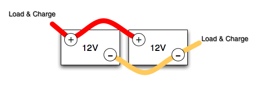
time2roll wrote:larry cad wrote:The main high amp connections are best made to opposite pairs. In your case say the main negative (-) went to the Trojans and the main positive (+) went to the Interstates would actually create a better balance. Especially under heavy loads or heavy charging. Yes the parallel connectors are low resistance and so are the batteries so it can cause 10% or more getting drawn from one set compared to the other.BFL13 wrote:I thought I answered that by explaining a jumper exists between the + and the - terminals. Theoretically the resistance between them is therefore 0 ohms which should do a fair job of balancing the loads from each bank. That they are close, and the "shunt" is short only improves that situation.
Yes they are in parallel. The question was if the load/charging is balanced across both pairs or not.
I would be interested in your calculation to support this statement. I assume you know the internal resistance of the two types of batteries, and also the resistance of the jumper wire between the two series sets of batteries. No doubt you included the resistance of the series jumpers as well.
By the way, the calculated resistance of the jumper wires, (both the series connections and the parallel connections) are .000047 ohms. If I were ever to pull full load (i.e. 400amps) through any one of those jumpers, the voltage drop calculates out to be .0188 volts DC which is .00156% of the 12vdc
Options
- Mark as New
- Bookmark
- Subscribe
- Mute
- Subscribe to RSS Feed
- Permalink
- Report Inappropriate Content
Mar-28-2021 05:14 AM
pianotuna wrote:
Hi Larry,
Treat each pair of six volt batteries as if they were a single twelve volt battery. Wire them in a balanced manner. (see below)
Yes, this is exactly what I have. Only difference is that I have 2 (two) positive feeds from the parallel set. One feeds my 12v fuse panel, and the other feeds my inverter/charger. One feed is connected from the rear positive post, and the other feed is connected from the front positive post. There is a jumper between those two positive posts consisting of 400 amp copper wire which serves to balance the loads. There is a single, negative wire which is firmly attached to the chassis of the coach.
Keep in mind that these batteries do not feed the motor starter as there are two more batteries to do that job and they are not connected to this array.
Options
- Mark as New
- Bookmark
- Subscribe
- Mute
- Subscribe to RSS Feed
- Permalink
- Report Inappropriate Content
Mar-28-2021 05:00 AM
BFL13 wrote:larry cad wrote:BFL13 wrote:
Yes they are in parallel. The question was if the load/charging is balanced across both pairs or not.
I thought I answered that by explaining a jumper exists between the + and the - terminals. Theoretically the resistance between them is therefore 0 ohms which should do a fair job of balancing the loads from each bank. That they are close, and the "shunt" is short only improves that situation.
Sorry, I don't understand what you mean. The OP photo is not clear to me either as there seems to be extra wires on the terminals. We may not be talking the same language wrt "balanced". I need to find a drawing of what I mean to link to at least clear that up. I will edit in here.
ok scroll down to 3.7 table 3 drawing of the four batts in series-parallel and note the position of the load/charge wires.
https://www.trojanbattery.com/pdf/TrojanBattery_UsersGuide.pdf
The drawing shows exactly what I have been saying, "series-parallel". Two 6 volt batteries in series, and the two sets of 6 volt series batteries are connected in parallel. Your suggested drawing is exactly what I have. You can actually see that in my photo.
Options
- Mark as New
- Bookmark
- Subscribe
- Mute
- Subscribe to RSS Feed
- Permalink
- Report Inappropriate Content
Mar-27-2021 08:54 PM
Hi Larry,
Treat each pair of six volt batteries as if they were a single twelve volt battery. Wire them in a balanced manner. (see below)
Treat each pair of six volt batteries as if they were a single twelve volt battery. Wire them in a balanced manner. (see below)
Regards, Don
My ride is a 28 foot Class C, 256 watts solar, 556 amp-hours of Telcom jars, 3000 watt Magnum hybrid inverter, Sola Basic Autoformer, Microair Easy Start.
My ride is a 28 foot Class C, 256 watts solar, 556 amp-hours of Telcom jars, 3000 watt Magnum hybrid inverter, Sola Basic Autoformer, Microair Easy Start.
Options
- Mark as New
- Bookmark
- Subscribe
- Mute
- Subscribe to RSS Feed
- Permalink
- Report Inappropriate Content
Mar-27-2021 04:00 PM
2oldman wrote:I have been using a watering system for about 10 years now. Makes this chore easier, faster and much safer.
My Trojans were thirsty too. Got tired of that and got AGMs.
I expect my next battery to be lithium.
Options
- Mark as New
- Bookmark
- Subscribe
- Mute
- Subscribe to RSS Feed
- Permalink
- Report Inappropriate Content
Mar-27-2021 03:57 PM
larry cad wrote:The main high amp connections are best made to opposite pairs. In your case say the main negative (-) went to the Trojans and the main positive (+) went to the Interstates would actually create a better balance. Especially under heavy loads or heavy charging. Yes the parallel connectors are low resistance and so are the batteries so it can cause 10% or more getting drawn from one set compared to the other.BFL13 wrote:I thought I answered that by explaining a jumper exists between the + and the - terminals. Theoretically the resistance between them is therefore 0 ohms which should do a fair job of balancing the loads from each bank. That they are close, and the "shunt" is short only improves that situation.
Yes they are in parallel. The question was if the load/charging is balanced across both pairs or not.


